




Clamping Force in Die Casting: Calculation and Machine Selection
Clamping force is one of the first technical figures compared when selecting a die casting machine. Yet a larger casting does not automatically require a proportionally larger machine simply because it weighs more. The relevant force results from the pressure acting on the effective projected area of the casting and its associated flow system. Die dimensions, shot capacity and process requirements must also match.
How is the required clamping force determined?
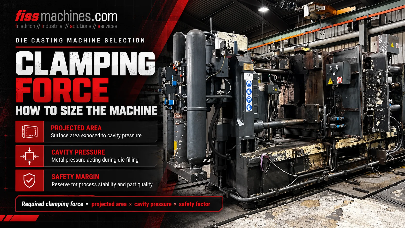
As a simplified first check, calculate the opening force from effective projected area × metal pressure. Apply an appropriate engineering allowance and compare the result with the machine's usable clamping capacity. The projected area is measured in the die parting-plane direction and must include the pressure-relevant regions of the complete gating and overflow system, not just the visible finished casting.
Why molten metal tends to open the closed die
During injection and pressure intensification, molten metal acts on the surfaces defining the filled cavity and the relevant feed system. The resulting force component in the die-opening direction tends to separate the two die halves.
The locking unit must counter this separating or opening force. If the available force is insufficient for the actual casting conditions, the parting surfaces may open locally and flash or other quality problems can develop.
Nominal machine clamping force is not the same as injection pressure. The two values describe different physical quantities. Equally, a machine with a high stated clamping-force rating may still be unsuitable because of platen geometry, tie-bar spacing, shot capacity or tool height.
Pressure in the die
The pressure acting on projected cavity and runner regions generates an opening load.
Effective pressure area
Relevant geometry is projected onto the die parting plane.
Machine closing capacity
The locking system opposes opening force within its rated operating limits.
What belongs to the projected area?
Projected area is the relevant area of the filled casting system as viewed in the opening direction, rather than the entire external surface area of a three-dimensional part. For the selected tooling, pressure-relevant gates, runners and overflow features must be considered along with the casting itself.
The technical literature also describes additional machine- and process-dependent pressure areas in the casting system. Therefore the exact effective area must be derived from the tooling and injection arrangement, rather than guessed from a photograph or part weight.
Two castings with different masses can require similar locking forces when their effective projected areas and casting pressures are similar. Conversely, a relatively light but flat and wide part can have substantial projected area.
A transparent example of clamping-force calculation
For a consistent set of units, a simplified opening-force estimate is Fopening [kN] = Aprojected [cm²] × pmetal [bar] / 100. The dimensional conversion results from 1 bar acting over 1 cm² corresponding to 10 N.
Consider a hypothetical effective projected area of 800 cm² and an assumed effective metal pressure of 600 bar. The resulting estimated opening force is 800 × 600 / 100 = 4,800 kN. If, purely as an illustration, an engineering allowance of 1.25 were selected, the comparison value would be 6,000 kN.
The allowance in this example is not a universal safety factor or a manufacturer-approved machine rating. Actual design must consider the die construction, core arrangements, true pressure history, injection unit, machine specification and the relevant engineering rules.
| Input | Illustrative value | Meaning |
|---|---|---|
| Effective projected area A | 800 cm² | Assumed pressure-relevant projected area |
| Metal pressure p | 600 bar | Assumed pressure acting in the filled system |
| Calculated opening force | 4,800 kN | 800 × 600 ÷ 100 |
| Illustrative allowance | 1.25 | Example only; not universally applicable |
| Illustrative comparison value | 6,000 kN | 4,800 × 1.25 |
Why the pressure value must be chosen carefully
Die casting injection has different speed and pressure phases. A hydraulic actuator reading cannot be substituted directly for effective metal pressure in the die without understanding the shot system, intensification mechanism and pressure transmission.
Metal pressure may change during cavity filling and solidification. Tool design, gate freezing, pressure peaks and the timing of intensification can all influence which loading condition is relevant for machine sizing.
For serious project work, use verified casting and machine data, process calculations and the responsible manufacturer or tooling engineer's specification instead of relying on a generic internet value.
Actuator-side quantity
Requires the correct machine conversion to relate it to metal pressure.
Casting-side quantity
Must be tied to the actual injection and intensification conditions.
Transient loading
Should be considered where relevant in tooling and process assessment.
Why a machine with enough clamping force may still be unsuitable
A machine must physically accommodate the die. Tie-bar clearance, platen dimensions, die mounting, minimum and maximum die height, opening stroke and ejector arrangement determine whether the tool can be operated.
The injection unit needs suitable shot capacity and stroke, a compatible shot sleeve or hot-chamber system and the correct process range for the alloy. The machine may also need hydraulic core-pulling circuits, vacuum interfaces, die temperature control and compatible extraction and spraying equipment.
A complete evaluation links part and tooling geometry to machine selection and to the desired production cycle. Nominal clamping force is only one part of that decision.
- Effective projected area including runner and overflow system
- Required metal-pressure and injection profile
- Nominal and usable clamping capacity
- Tie-bar spacing and usable platen area
- Permitted die height and required opening stroke
- Shot capacity, sleeve or injection-system configuration
- Ejector and core-pulling functions
- Temperature-control, vacuum and automation connections
What to inspect on a used machine with the required force class
On a used die casting machine, confirm the actual model, declared clamping-force rating and technical condition. Examine tie-bars, platens, toggle or hydraulic locking components, central lubrication, locking position feedback and any relevant maintenance history.
A machine should be inspected under appropriate operating conditions where possible. However, a clean visual result or a stated nameplate value alone cannot prove full casting performance with a new die.
FISS offers used cold-chamber and hot-chamber machines of different sizes as well as complete casting cells. The final configuration should be selected from verified tooling and production requirements.
Frequently Asked Questions About Die Casting Clamping Force
What is the difference between clamping force and injection pressure?
Clamping force is a mechanical force opposing die opening, typically stated in kN. Injection or metal pressure is pressure applied to the melt and is typically stated in bar or MPa.
Does the weight of the casting determine the machine size?
Not on its own. Effective projected area and metal pressure govern the basic opening-force calculation. Shot capacity and geometry are additional requirements.
Does a core slide affect machine selection?
Yes. Slide geometry and locking can influence local tooling loads and the applicable design allowance; hydraulic circuits and control functions must also match.
Is an allowance of 1.25 always required?
No. The figure in the example is illustrative. Applicable allowances depend on the engineering method, die construction and machine/tool specifications.
Is enough clamping force sufficient to approve a used machine?
No. Tie-bar spacing, platens, die height, opening stroke, shot unit, ejectors, core pulling, automation, safety and actual machine condition also require checking.
Choose a used die casting machine by verified technical data
FISS supports international purchase and sale of used cold-chamber and hot-chamber machines. Compare the calculated process requirements with the complete machine specification and condition.
View Used Die Casting MachinesTechnical basis and sources
Technical formula and projected-area principle: Handbuch Urformen, section 1.6.4.1.1, equations 1.45–1.46. Example numbers are explicitly hypothetical; allowances are not general design approval. Original text and example.
