




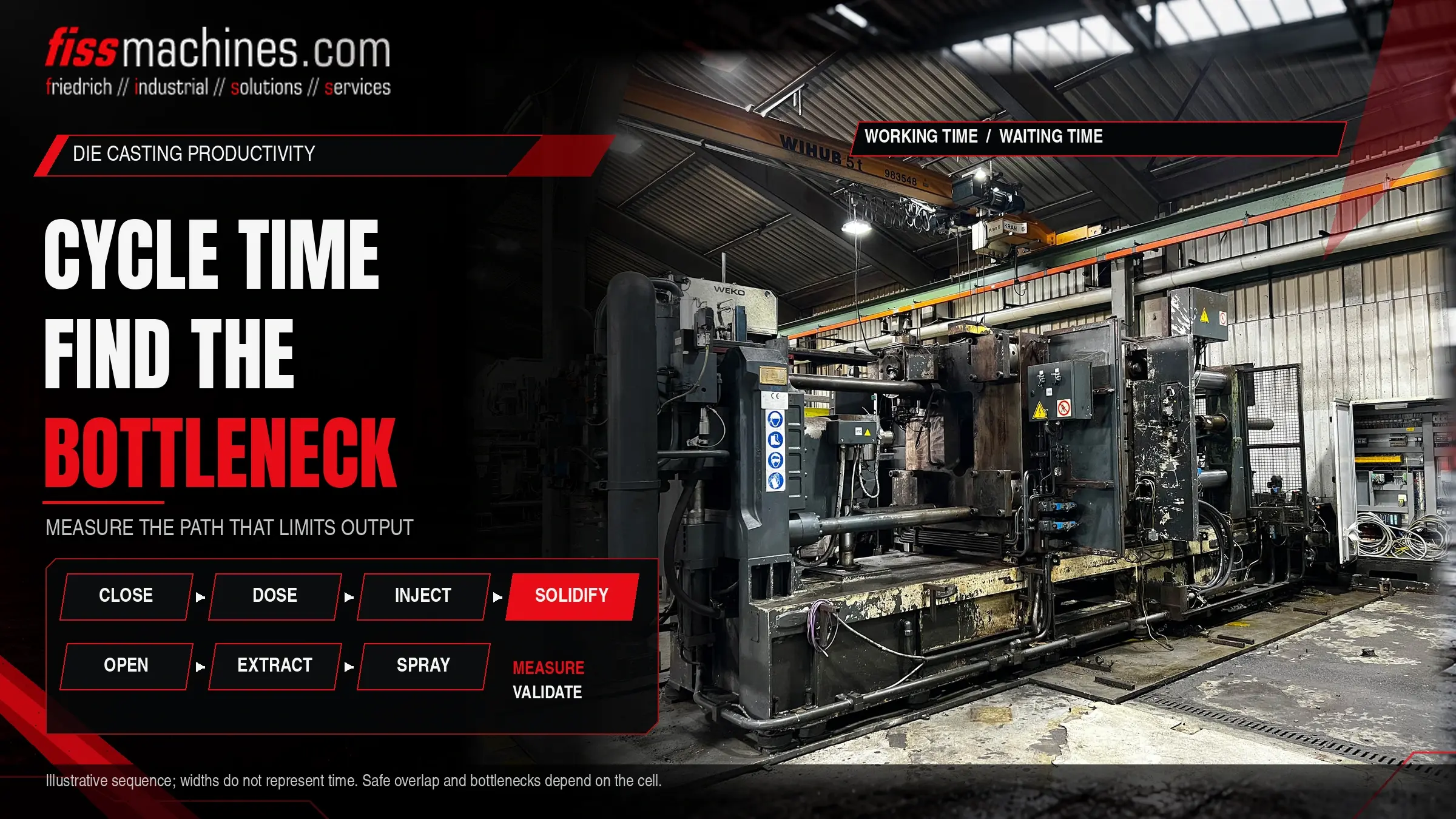
Die Casting Cycle Time: Identifying Bottlenecks and Improving Sequences
The cycle time of a die casting cell decides how many parts a shift can produce, and therefore how much a machine hour really costs. Yet the figure shown on the machine display rarely explains where the time goes. Die closing, dosing, shot, solidification, opening, extraction, spraying and handling all compete for the same seconds. Finding the step that actually limits output, and shortening it without hurting quality, is a systematic task rather than a matter of turning every setting faster.
How Do You Find the Bottleneck in a Die Casting Cycle?
Break the cycle into its individual steps, measure the duration of each over many shots and mark which steps run in sequence and which run in parallel. The bottleneck is the step on the sequential path, the critical path, that takes the most time or varies the most. Only shortening that step reduces the cycle; accelerating parallel steps changes nothing.
Solidification time is often the largest single block, but it is tied to part quality and die temperature. Gains are usually easier to find in waiting times, handling and spraying sequences.
What a Die Casting Cycle Consists Of
The exact order depends on machine type, part and automation, but a cold chamber cell typically runs through the steps below. In hot chamber machines, dosing is replaced by the gooseneck filling, which shortens that part of the sequence considerably.
| Element | Main drivers | Typical levers | Risk if shortened carelessly |
|---|---|---|---|
| Die closing and locking | Platen stroke, speed profile, die protection phase | Optimised strokes and speed transitions | Die protection less effective, impacts on die |
| Dosing and pouring | Ladle travel or dosing furnace, shot weight | Start dosing earlier, parallel to die closing where safe | Metal cools in the sleeve, inconsistent biscuit |
| Shot and intensification | Process requirements of the part | Usually very little; not a typical bottleneck | Direct effect on filling and porosity |
| Solidification (die closed) | Wall thickness, alloy, die temperature, cooling layout | Die cooling and thermal balance, local cooling | Distortion, hot tears, ejection problems |
| Die opening, core pulls, ejection | Strokes, slide sequences, ejector movement | Overlapping movements where the control allows it | Collisions, damage to slides or casting |
| Extraction | Robot or extractor path, gripping, part check | Shorter paths, earlier entry into the die area | Collision risk, unstable gripping |
| Spraying and blow-off | Die size, spray pattern, thermal requirements | Optimised spray programme, less but targeted spraying | Soldering, sticking, changed die temperature |
Measuring the Cycle Correctly
A single stopwatch reading is not enough. Cycle steps vary, and occasional long waits often cost more than a slightly slow movement. The most useful data comes from time stamps of control signals, which many machine and robot controls can log. Where this is not possible, video recording of several cycles is a practical alternative.
Define start and end of each step
Use clear signals such as "die locked" or "robot clear of die area" so that the same step is measured the same way every time.
Record many cycles
Capture a representative period including normal disturbances. Average values hide variation; look at spread and outliers too.
Draw the sequence
A simple time bar chart shows which steps overlap and which wait for one another. The longest chain of dependent steps is the critical path.
Separate waiting from working
Mark every period in which a unit is ready but waits for a signal. Waiting time is often the cheapest time to remove.
Typical Bottlenecks in Practice
Solidification and die temperature
The time the die stays closed is governed by the thickest sections and by how well the die removes heat. Shortening it without improving cooling risks distortion or ejection problems. Real gains here usually come from the die: cooling channels, local cooling or a more balanced thermal layout, often combined with an adapted temperature control unit.
Spraying
Spraying cools and protects the die surface, so it is both a time block and a thermal tool. A spray programme that has grown over years often contains redundant passes. Reducing it has to be checked against die temperature and sticking.
Peripheral equipment and handshakes
Extraction robots, sprayers, trimming presses and conveyors communicate with the machine through signals. Conservative interlocks or slow handshakes add seconds that appear nowhere in the machine settings. Our article on automation in the die casting cell describes the typical peripheral units and their tasks.
Dosing
If the ladle or dosing furnace cannot keep up, the machine waits with the die closed or the sleeve empty. Dosing capacity and accuracy should therefore be checked as part of any cycle analysis. The differences between furnace types are covered in Dosing, Melting or Holding Furnace?
Improving the Sequence Without Risking Quality
Sequence improvements work best as controlled experiments. Change one thing at a time, run long enough to reach thermal equilibrium and compare cycle time, scrap rate and casting quality before and after.
Usually low risk
Removing unnecessary waiting times, starting movements in parallel where the control and safety concept allow it, shortening robot paths and correcting slow handshakes between machine and periphery.
Needs careful validation
Reducing solidification time, changing spray quantity or pattern, and increasing movement speeds near the die. These affect die temperature, part quality and wear and should be tested with inspection of the castings.
Overlapping movements must stay within the machine's safety concept. Interlocks and guard functions should never be bypassed to gain cycle time; changes to safety-related logic need a qualified assessment.
Cycle Time, Downtime and OEE
A shorter cycle only pays off if the cell actually runs. Overall equipment effectiveness (OEE) combines availability, performance and quality. A cell with a fast cycle but frequent stops, long die changes or high scrap can produce less than a slower, stable one. It is therefore worth looking at stoppage reasons and scrap alongside the cycle analysis.
OEE = Availability × Performance × Quality
Availability = run time / planned production time; Performance = (ideal cycle time × parts produced) / run time; Quality = good parts / parts produced. All three as fractions between 0 and 1.
Checklist for a Cycle Time Analysis
- Start and end signals defined for every cycle step
- Data recorded over many cycles, including disturbances
- Critical path identified; parallel steps marked separately
- Waiting times between machine, robot, sprayer and press quantified
- Solidification time assessed together with die cooling and temperature
- Spray programme reviewed for redundant passes
- Dosing capacity and accuracy checked against cycle target
- Downstream steps (trimming, cooling, conveyors) checked for capacity
- Each change tested alone and evaluated with scrap and quality data
- Safety concept respected for every overlapping movement
Frequently Asked Questions
Is a faster machine the easiest way to cut cycle time?
Rarely. Machine movements are often a small part of the cycle compared with solidification, spraying and handling. A faster machine helps only if its movements are on the critical path.
Why did cycle time get worse after a die change?
Different dies have different thermal behaviour, spray programmes and slide sequences. Each die needs its own analysis; settings from another die are only a starting point.
Can the trimming press limit the cell?
Yes. If the press, a cooling station or a conveyor cannot take the part in time, the robot waits and the machine waits with it. The bottleneck may lie outside the casting machine.
FISS Helps You Find Suitable Machines and Equipment.
If your analysis shows that a machine, furnace or peripheral unit limits output, FISS can help you review suitable used equipment for your part and cycle target.
