




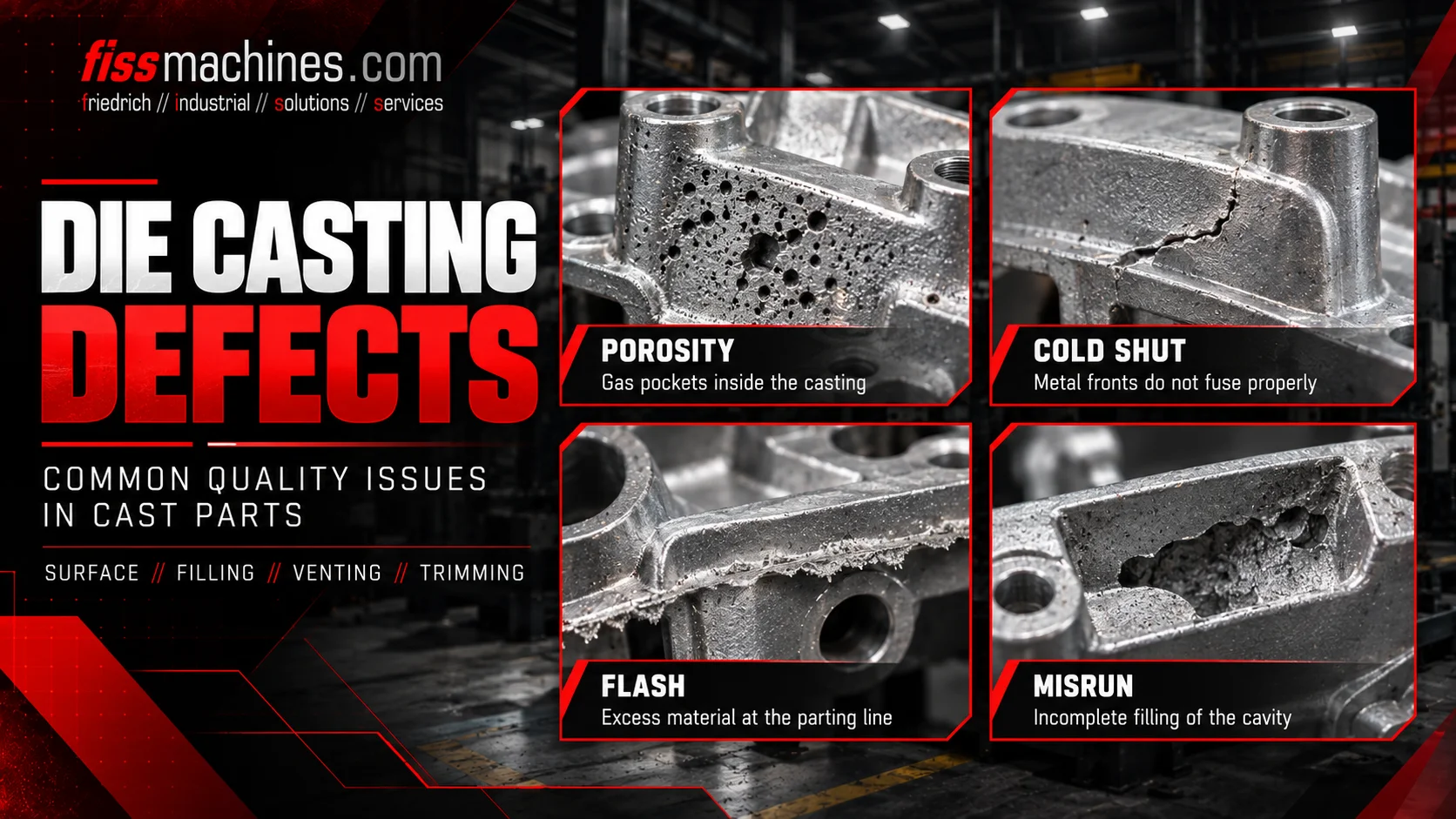
Die Casting Defects Explained: Porosity, Shrinkage, Cold Shuts and Blisters
A visually acceptable die casting can still contain pores, shrinkage cavities or local imperfections. Some defects become visible only after CNC machining, heat exposure or a leak test. Consistent quality therefore requires more than inspecting the surface: metal preparation, shot profile, die venting, temperature control and the condition of the casting equipment must be assessed as a connected process.
What are the most common defects in high-pressure die casting?
Important defect groups include gas porosity caused by trapped or released gases, shrinkage porosity associated with solidification contraction, cold shuts where melt fronts fail to unite properly, misruns where the cavity is not fully filled, and blisters that may become visible after heating. Their appearance alone is not always sufficient for a reliable root-cause diagnosis.
Why a defect name is not yet a diagnosis
The same visual symptom may be linked to different causes. A pore may originate from trapped air, gases released by residues, melt treatment or volumetric shrinkage during solidification. Different mechanisms can also occur in the same casting.
Root-cause analysis must connect the location and morphology of a defect with the shot curve, runner and vent layout, melt quality, die temperature, spraying recipe and downstream processing. Reducing all defects to a single pressure or temperature setting leads to unreliable corrections.
| Defect | Typical observation | Potential contributing factors |
|---|---|---|
| Gas porosity | Gas-filled voids, sometimes rounded | Air entrainment, process gases, limited venting or melt-related gases |
| Shrinkage porosity | Voids associated with contraction during solidification | Hot spots, feeding limitations, pressure transmission and solidification path |
| Cold shut | Seam or line where two metal fronts meet | Premature cooling, oxide films and unfavorable filling path |
| Misrun | Unfilled part of the cavity | Insufficient fluidity or inadequate filling conditions |
| Blister | Raised surface bubble, often after heat exposure | Expansion of internal trapped gas near the surface |
Gas porosity: where does the trapped gas come from?
In cold-chamber machines, inappropriate initial plunger motion can create overturning melt waves in the shot sleeve and entrap air before the metal reaches the gate. Additional air in the runner and cavity must escape during the very short filling phase.
Gases can also form when release-agent or lubricant residues are heated. Local vent obstruction may increase the amount of gas remaining in the casting. Melt cleanliness and dissolved gas content must also be considered for the processed alloy.
Venting systems, overflow pockets and where appropriate vacuum assistance aim to reduce gas entrapment. None of them automatically compensates for an unfavorable filling profile or excessive spray residues.
Controlled first phase
Avoid unsuitable melt waves and their associated air entrapment.
Open gas paths
Inspect vents, overflow regions and vacuum interfaces where installed.
Repeatable application
Avoid excessive residues and uncontrolled gas generation.
How shrinkage cavities differ from gas pores
Liquid metal contracts as it cools and solidifies. Where the solidification sequence and pressure transmission cannot compensate for this volume change, local shrinkage voids or microporosity can form.
In practice, the distinction between gas and shrinkage porosity can be difficult, especially when mechanisms overlap. Shape and location give clues but may not prove the origin. Metallographic evaluation, radiography or CT combined with process analysis can be needed.
Important factors include die temperature, section thickness, local hot spots, gate freezing, pressure timing and the overall filling design. A higher intensification setting alone does not guarantee an improvement if the pressure cannot be transmitted to the affected zone.
Cold shuts and misruns: related, but not identical
A cold shut occurs when adjacent metal streams meet without forming a sound bond. It may appear as a visible line or seam. Oxide films, local cooling and the meeting angle and velocity of the metal fronts can contribute.
A misrun means that the cavity has not been filled completely; a corner, thin rib or other feature remains missing. Possible contributors include insufficient metal temperature, unsuitable gate and runner design, excessive flow resistance or insufficient filling performance.
The appropriate corrective action depends on the actual filling mechanism. Reviewing simulation results, die temperatures and injection curves can be more useful than adjusting a single machine parameter without evidence.
Incomplete joining
Two fronts meet but fail to fuse into a sound continuous region.
Incomplete filling
The melt fails to reach or fill the complete cavity.
Compare evidence
Match defect location with flow direction, temperature and shot data.
Why blisters may appear after heating
Gas trapped close to the surface can expand during subsequent heating and create a local raised area or blister. This is particularly relevant when thermal post-processing is planned, because high-pressure die castings with substantial gas entrapment may be unsuitable for certain heat-treatment conditions.
The risk depends on alloy, casting quality, gas location, temperature and process history. Not every surface blister has exactly the same cause, so a sectioned sample and relevant process records can help distinguish gas-related blisters from other surface damage.
Preventive attention starts upstream: controlled filling, suitable venting, an adapted release-agent process and a stable die temperature.
Which tests help identify defects reliably?
Visual inspection and dimensional checks are useful for surface defects, but internal porosity requires additional methods. Depending on the component and its acceptance criteria, X-ray inspection, industrial computed tomography, sectioning, metallography, density assessment or leak testing may be appropriate.
Choose the measurement method for the functional requirement. A sealing surface, structural region and cosmetic part may require different acceptance criteria; simply counting every pore as equally critical would be misleading.
For recurring defects, document the cavity position, shot number, temperature conditions, operator changes and machine curves. Correlating these records is often more informative than inspecting isolated rejects.
- Locate the defect on a defined part drawing
- Classify whether the observation is surface or internal
- Check melt handling, dosing and shot profile
- Inspect die vents, overflows and any vacuum system
- Review spray recipe and thermal condition of the die
- Select a suitable verification method for the required function
- Record corrective actions and compare measured results
How the condition of the casting cell affects quality consistency
Machine condition matters when pressure and velocity must be repeated over thousands of cycles. Worn injection components, unstable hydraulics, malfunctioning die temperature-control equipment or unreliable interfaces between dosing, spraying and extraction can contribute to process variability.
When inspecting a used die casting machine or complete cell, verify the injection system and the availability of process records as well as nominal clamping force and shot capacity. FISS supports the international purchase and sale of used casting machines and automation.
Frequently Asked Questions About Die Casting Defects
Are gas porosity and shrinkage porosity the same?
No. Gas porosity is associated with trapped or released gases; shrinkage porosity is linked to solidification contraction and insufficient local compensation. Mixed forms can occur.
Can X-ray inspection detect every defect?
No single method detects every defect under all conditions. Detectability depends on defect size, location, material thickness and inspection method.
Why do cold shuts form?
They can develop when separate metal fronts meet without a sound bond, for example due to temperature loss, oxide films or an unfavorable flow pattern.
Does raising injection pressure eliminate shrinkage defects?
Not automatically. The effect depends on pressure timing, gate solidification, feeding and the local thermal conditions.
Can blisters occur after heat treatment?
Yes. Trapped gases close to a casting surface can expand during heating and form visible blisters, depending on the alloy and processing conditions.
Assess your die casting machine and process requirements
FISS offers used die casting machines, equipment and complete casting cells. For reliable selection, compare process demands, injection-system condition and available automation.
Explore Used Die Casting MachinesTechnical basis and sources
Technical background: Handbuch Urformen, sections 1.6.4.1.2 (filling), 1.6.4.1.4 (venting) and 1.8 (quality/simulation). Inspection methods and root-cause guidance are general engineering context, not an unverified diagnosis. Original text.
