




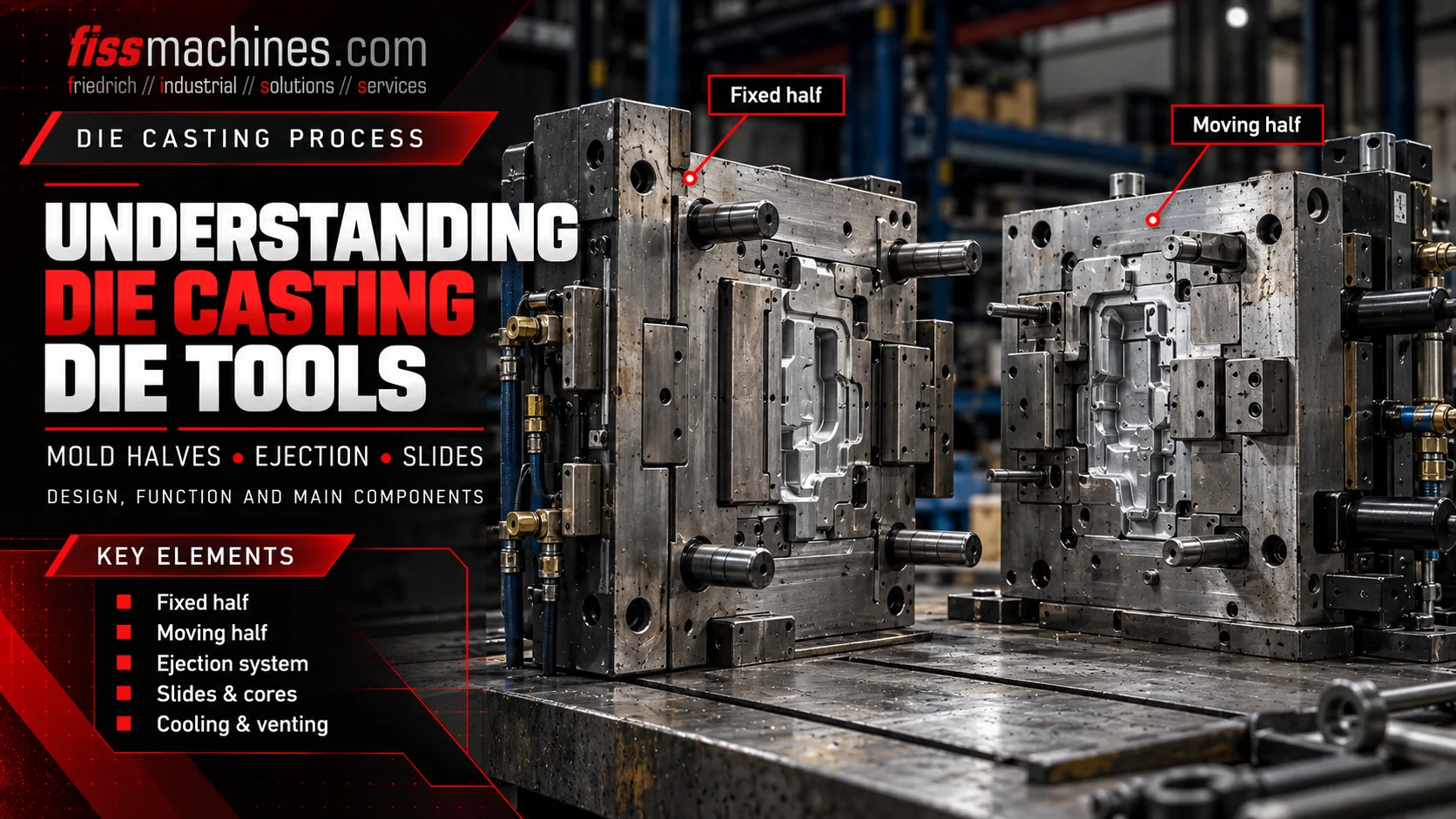
Understanding Die Casting Dies: Fixed and Moving Halves, Ejectors and Slides
A die casting die is a precision tool that shapes liquid metal under pressure. Its main elements must work together: the fixed die half introduces the melt, the moving half opens with the machine, ejectors remove the solidified casting, and slides form features that cannot be released in the main opening direction. Understanding these elements also helps when choosing a suitable used die casting machine.
What are the main components of a die casting die?
A typical high-pressure die casting die consists of a fixed, injection-side half and a moving, ejector-side half. It may also include die inserts, runners and gates, overflow and venting features, cooling or temperature-control circuits, ejector pins and mechanically or hydraulically actuated slides. The exact arrangement depends on the casting and tooling concept.
How the two die halves work together
The fixed die half is mounted on the stationary machine platen, on the injection side. The moving die half is mounted on the moving platen and normally houses the casting ejection system. Both halves meet at the parting surface and are held closed by the machine during injection.
The cavity is formed by the shaped surfaces of both halves and, where required, additional cores and moving elements. Die inserts allow highly loaded or detailed regions to be manufactured, maintained or replaced separately. The machine opens the die after the necessary solidification time; the casting is then released and removed.
A technical drawing should distinguish the cavity-facing surface from the rear side of the moving half. Ejector pins usually approach the casting from behind the moving-side die insert; they do not enter the tool from the parting line as loose external components.
Injection-side assembly
Mounted to the stationary platen; often incorporates the metal-entry region and part of the cavity.
Ejector-side assembly
Moves during machine opening and generally contains the ejector system behind the forming surface.
Defined closing interface
The contacting surfaces must close accurately and support controlled metal containment and venting.
How ejector pins and ejector plates release the casting
Once the die opens and any relevant slides have been retracted, the casting must be separated from the tool. The ejector assembly normally consists of ejector pins supported by one or more ejector plates, guiding elements and a drive or coupling to the machine ejector mechanism.
During ejection, the plates move the pins forward through correctly fitted bores in the moving half. The pin faces push on selected casting locations, ideally distributing force without damaging thin walls or functional surfaces. Afterwards the system returns before the next closing movement.
Typical problems include stuck pins, insufficient lubrication, uneven ejection or visible pin marks. These symptoms require evaluation of tool temperature, alignment, pin clearance, casting geometry and operating sequence rather than simply increasing ejection force.
When are slides and cores necessary?
Features such as transverse holes, side openings and undercuts cannot always be released along the main die-opening direction. Moving cores, often called slides or core slides, are used to form these geometries.
Depending on the construction, a slide may be actuated mechanically by the die movement or by a hydraulic drive. It must reach its intended forming position before casting and retract at the defined point in the opening and ejection sequence.
Wear in slide guides, locking surfaces or seals can lead to dimensional deviations, leakage or a blocked tool. Used-machine selection must therefore consider the machine's available hydraulic core-pulling circuits and control functions.
Forms lateral openings
Creates geometry that would otherwise prevent direct part release.
Controls motion
Constrains movement and supports repeatable positioning.
Resists pressure
Supports the core against forces acting during metal filling.
Runners, gates, vents and temperature-control circuits
The runner and gate system guides molten metal to the cavity. Its design influences filling behavior and the amount of material later removed as runners and gates. Overflow pockets and correctly designed vents help manage flow and allow air and process gases to leave the cavity.
Temperature-control channels in the tooling circulate suitable media to influence die temperature and local solidification conditions. External die spraying complements, but does not replace, internal temperature control. Too much release-agent residue can also impair venting performance.
All these elements form one connected process: changing gate geometry, venting, local cooling or spray conditions can change the casting outcome. That is why the die should be evaluated together with its casting parameters rather than as an isolated mechanical component.
| Die element | Primary function | Typical check |
|---|---|---|
| Runner and gate | Direct melt into the cavity | Damage, deposits, erosion and intended flow path |
| Overflow and vent | Manage last-fill regions and remove gases | Deposits, obstruction and wear |
| Temperature-control circuit | Control local thermal conditions | Leak tightness, flow and connections |
| Forming inserts | Produce the required casting geometry | Cracks, erosion, wear and alignment |
A simplified sequence from closing to ejection
A coordinated die casting cycle normally brings the movable cores into position, closes and locks the die, fills the cavity and applies the required holding or intensification conditions. Following solidification, cores are withdrawn as required, the die opens and the casting is ejected and removed.
The precise order can differ by machine, die and application. For example, some side cores move at different points before, during or after opening. Interlocks ensure that the machine does not close while ejectors, slides, robots or spray tools occupy an unsafe position.
- Confirm slide and core positions before closing
- Confirm ejectors are back before the next shot
- Verify removal and spray units have left the die area
- Monitor tool temperatures and cooling-media flow
- Keep parting surfaces and venting features clean
What must match between die and die casting machine?
For a machine change or a used-machine purchase, die dimensions and mass are only the beginning. Platen size, tie-bar spacing, required opening stroke, die height or thickness range and ejector coupling must be compatible with the actual tooling.
The machine also needs sufficient clamping force for the projected area and casting pressure, appropriate shot capacity, the required core-pulling circuits and suitable process connections. A matching nominal clamping-force class alone does not prove that a given die can be installed.
FISS offers used cold-chamber and hot-chamber die casting machines and associated automation. Equipment availability and machine-specific suitability must always be checked against the actual project data.
Frequently Asked Questions About Die Casting Dies
What is the difference between the fixed and moving die halves?
The fixed half stays on the stationary platen on the injection side. The moving half opens with the moving platen and normally contains the ejector assembly.
Where are ejector pins installed?
In a typical high-pressure die casting die, ejector pins are supported by ejector plates behind the moving-side forming surfaces and pass through fitted bores to push the casting out.
Why are slides used?
Slides and moving cores form holes, undercuts and side features that cannot be released in the main die-opening direction.
Is every die equipped with hydraulic slides?
No. Many castings can be released without moving cores; other tools use mechanical movements, hydraulic slides or a combination.
Can a die be installed on any machine with adequate clamping force?
No. Platen and tie-bar geometry, opening and ejection strokes, shot capacity, media connections, core-pulling equipment and controls must also match.
Looking for a suitable die casting machine?
FISS supports the purchase and sale of used die casting machines and complete casting cells. Compare the actual die data and production requirements with the available equipment.
View Used Die Casting MachinesTechnical basis and sources
Technical fundamentals: Bührig-Polaczek, Michaeli and Spur (eds.), Handbuch Urformen, section 1.6.4, Carl Hanser Verlag. FISS machine category and technical selection information. Original text; no copyrighted figures reproduced.
